Ford Kuga Owners Club Forums banner

Rear Footwell lights

19K views 45 replies 8 participants last post by  The Ace  
#1 ·
Connected up my rear footwell lights tonight. Had them in my previous MK2 but of course the current Kuga has ambient lights, so thought I'd modify my rear footwell lights to become ambient lights too. These are fitted to the underside of the front seats.

The ambient mode doesnt look that bright in the images but they are as bright as the standard front ambient lights.

As the front footwell lights are combined ambient/footwell and arnt particularly bright compared to the custom LEDs I had in the previous MK2, I fitted additional front footwell lights under the front seats that also dim in ambient mode.

Image

Rear Footwell lights in normal and ambient mode.


Image

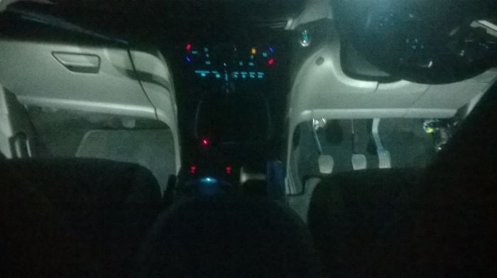
Front footwell in normal mode.

Image

Front passenger showing Normal and ambient mode.
 
#3 ·
Hi Brett, I actually made mine on a PCB but they are special because they have the ambient switching on them.

If you already have footwell lights and not ambient lighting, you can wire then rear footwell lights to one of the front ones or even to your boot light. Any small LED lamp assembly will do, even those strips you see around, though I've never used them. My lamps are fitted to the top of the heater outlet under the front seats.
 
#5 ·
Ford has managed the impossible: front and rear of the car's cabin seem to be from entirely different cars, since doors, seats, lights etc are completey different (much worse in the rear). I do think that the rear seats need a bit of (ambient) lighting, so would it be possible to get two additional light assemblies of the front footwells (1757821 ?), install them under the front seats and wire them to the front lights ?
 
#6 ·
First of all sorry Brett (Spiers3), didnt see your post above.

Oddly enough, though maybe not, it seems in the US they have rear footwell lights, but no rear door handle lights. But why Ford don't think you need lighting in the rear footwell's is strange. Similarly lack of heated rear seats to me.

If you have standard footwell lights i.e not ambient light version, you could obtain any 12V LED lamp assembly for the rear footwell and wire it to a front footwell, or even to the boot light. I've always fitted my rear footwell light under the front seats (Orion, Mondeo's and Kuga). You only ned to wire to one front footwell light for both rears.

If you have the OE ambient lighting, you could obtain 2 ambient lighting footwell lights assemblies and wire them to one of the front footwell ambient lighting units, ensuring you connect the 3 wires correctly. They do have a plug ans socket arrangement.

While my Kuga does have ambient lighting I didnt think it was bright enough, so opted for adding additional LEDs as per the images above which switch lighting levels between ambient and door open. These are controlled by the boot light, but this isn't simply a matter of putting an LED across the boot light, like the OE ambient lighting, there is some electronics on the light assembles I made.


Edited by: Fillco
 
#7 ·
The US model has rear foot well lights ? Can't seem to find the finis for them, maybe cause the sites I got for Ford are all european ?

My ST-L has ambient, although only in the front. I've seen the 1757821 light assembly and its three-wire connector, so it should be just a pin-for-pin (in parallel) connection to the front footwell lights, right ?

I actually think that the maximum setting for the ambient is too bright, I always set the slider at about 55-60%.
 
#8 ·
The reason I say the US model had them they are shown on a wiring diagram I have for the MK2 Escape. To be honest, they may or may not have fitted them but they are shown.

Yes the wiring diagram shows all the ambient lighting units are pin to pin and to one point so should be a diddly doddle to fit.

Edited by: Fillco
 
#10 ·
And under the seat too. Magic Anthony.

He'd no reason to go up
to the BCM he could Scotchlock Quick Splice Snap Click Male Tab Spade
Connection (RED) into the cables in the footwell and what's with the
soldering iron.

You dont need to remove the skirting either, cables will easily push up underneath the skirting and route to underneath the seat.
Edited by: Fillco
 
#12 ·
More or less yes, that should do it. I've already located the finis for the front LED fixtures, I've gottten a quote from my Ford shop, and I'm just itching to do this mod
Image


Only thing left to do is locate/source the correct connectors, the correct one is 2-1718346, but I've managed to find only the 1-1718346...
 
#14 ·
After listening to the kids bugging me for many weeks ("dad, how come it's so dark back here ?") I've finally sourced the connectors and pins on Ali, ordered them and waiting to receive them. I've also confirmed availability of the fixtures, so everything's set, I'll be doing this in the next couple of weeks...
 
#15 ·
Well, bollocks, Ambient-Ace: one-nil :( Finally all pieces arrived (had to wait 1,5+1,5 months for the correct pins to arrive from China), made all wiring and connections, unfortunatelly my T-clamps were too big for the stock wiring, so a chance for Stanley's FatMax Stripper to shine ;), tested continuity to make sure all wires were good, went to the car and.....nothing. Neither LED would light up, and I tested both for proper functionality by exchanging them with the stock ones. While connected, the original socket lights up just fine, it's just the additional wiring+LED that stay dark. Only thing I noticed was that voltage between the three additional wires was fluctuating, which I don't think it should, so probably a bad t-tap wiring ?

Any suggestions for my next attempt ? Any chance it's something other than a failed connection ? Geez, I hate it when I fail at something so simple...
 
#18 ·
Ace what size/colour of T tap (scotchlock?) have you used? Voltage fluctuating may be because your measuring the high frequency pulses to the light as they are not simply switched on they are pulsed to provide the dimming function.
 
#19 ·
I first tried to use the smaller scotchlocks I had, which should be good for 0,5-1,5mm wires, but they failed (or so it seemed, since the LEDs wouldn't light up) to make a proper connection to the stock wires. So I removed these and just directly t-spliced into the wires using Stanley's FatMax Auto Stripper.

If I should indeed be looking at fluctuating voltages between the three wires, then I'm completely baffled as to why it's not working as it should. Only thing left to test is whether the pins of the LED are actually making contact with the terminals inside the connector...
 
#20 ·
OK, yes the wires I think are less than 0.5mm and the small red scotchlocks may still be too large so not have displaced the insulation and made contact with the conductor.


So you have fluctuation on the end of the three wires?

Pin 1 I think looks like its a positive to the light module.

Pin 2 looks like its the Linear pulsed signal.

Pin 3 of the connector which may be a black wire is ground.

Does that help?
 
#21 ·
Indeed I think you are correct, If I remember correctly the colors and stripes, Pin1 is orange-white and should be constant (+), middle Pin2 is yellow-white and is the one I first noticed the fluctuation, and Pin3 is mostly black, and should be ground. My next attempt will be to check all voltages to both the stock and the additional connectors, and also try to verify that all connectors and pins are making contact. In fact the constant wire stays alive long after you have switched off, closed door and locked car.

My next wild guess why this isn't working, is that there is some sort of interference due to different gauge wires, stock wires look smaller than 22AWG, while the additional wires I used are either 20 or 18AWG
 
#22 ·
Yes it will stay live as lights are on the battery saver circuit so will go off when that times out.


Well all the ambient lighting is simply tapped off and appears to be no particular special structure and the pulse frequency is so low it should have problems with what would be called standing wave issues with cable gauge or length etc.


This is going to be something simple and they are usually harder to find.


With your additional wires attached do the original/existing ambient lights work OK?
 
  • Like
Reactions: RonnieM
#23 ·
Yes, they work just fine, they don't even flicker, or dim, or change, or give out any other indication that something might be wrong. Which is why this is even more baffling, since everything looks OK, continuity is verified, connections seem solid, voltages are present in both connectors, however only one (stock) lights up while the other stays dark. All LEDs are operational when connected to the stock connector.

Thanks for the english term btw ;)
 
#24 ·
Are you measuring the voltage actually with a device plugged in on your additional wires and actually on the device itself if possible
 
#25 ·
So I'm not confused. the two original ambient lights work OK in their original positions?
 
#26 ·
All four fixtures work OK when connected to the stock connectors, and none works in the additional ones. So it is clearly something in the wiring/terminals/connectors I added (which I'm failiing miserably to identify :( ).

So far, I'm measuring voltages in the connectors with the second (additional) fixture off, so without load. I'll try to measure with and without, to compare.